

Files (3)
Choose the needed variant and slice it; source file size is not printable volume.
Use the slicer's filament total; STL/3MF byte size is not a cost input.
Slice with the recommended material, infill, orientation, and supports.
| STL file | Role | Source size | PETG 20% | PETG 25% | 100% solid | Recommendation |
|---|---|---|---|---|---|---|
| 2012_STI_Wireless_Charging_Mod_part_1.stl | Printable file | 73.5 KB STL | Slice file | Slice file | Slice file | Ensure proper ventilation when printing with PETG |
| 2012_STI_Wireless_Charging_Mod_part_2.stl | Printable file | 63.9 KB STL | Slice file | Slice file | Slice file | Ensure proper ventilation when printing with PETG |
| 2012_STI_Wireless_Charging_Mod_part_3.stl | Printable file | 37.0 KB STL | Slice file | Slice file | Slice file | Ensure proper ventilation when printing with PETG |
Saved setup guidance is used for material, infill, support, and per-file recommendation text; editable numbers are planning estimates only.
2008-2014 Subaru WRX/STI Wireless Charging Mod

Shared by
3DPrintedCarPartDescription
QI Wireless Charging Mod for 2012 Subaru STI Built around this wireless charging pad. Application Notes: For all printed parts, use a high temp plastic such as PETG - cars get hot. Device is secured in place by wedges that fit onto the plastic ribbing of the original Subaru center console part (part 1 to print). These are then glued in place using PETG compatible glue such as acrylic glue. Foam tape is stuck to the magnetic back of the charging module to apply outward pressure from frame against back of charge mat. Box containing the electronics can be screwed together. 2mm self tapping screws can be screwed through the lid, holes in the PCB and into the lower case half. Ensure the blue LED is positioned in the hole and wires tucked behind circuit board. The box containing electronics can then be folded down and glued on top of the ladder frame assembly. If car is used in a humid climate, it is recommended to spray circuit board with electronics conformal coating. Or alternatively use a compatible silicone to seal up the wire passthrough gap. Once installing in car, you can access the 12v supply for the cigarette lighter (accessory) power. It is located behind the radio bezel / HVAC controls. You can use wire splice connectors to tap into the Yellow/Green and Black wires on the 4 pin connector (i24 in service manual). It is clipped into the dash plastic center immediately behind the HVAC module. Once disconnected, I routed the wires down under the cigarette lighter to have space to install the splice connectors. Wrap everything in tape and install optionally a disconnect (e.g. bullet connectors) to be able to take out the center console in future easily.
Compatible Cars
Originally published on thingiverse.com by Chris Hughes (QB89Dragon) · License: CC BY
Share whether this print actually fits a real car. Installed photos and material notes make the catalog more trustworthy.
Related Parts
Most specific car + model + year + category matches first, with popular parts mixed in.

WRX STI USB Plate
License: CC BY-NC
View STL source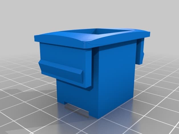
USB insert for 2006 Subaru WRX
License: CC BY
View & download STL files
2013 Subaru Impreza/Crosstrek–Compatible Center Console Tray
License: CC BY
View & download STL files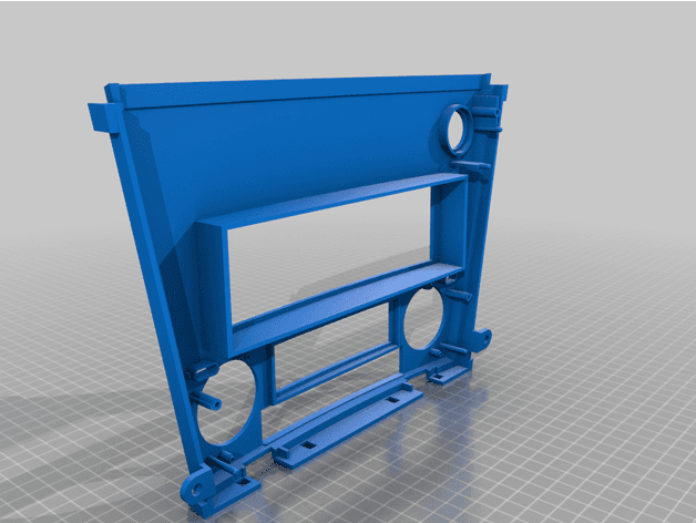
SUBARU LEGACY 2006-2009 1DIN PANEL
License: CC BY
View & download STL files
Subaru BRZ/Toyota GT86 Center Console Fire Extinguisher
License: CC BY-NC
View STL source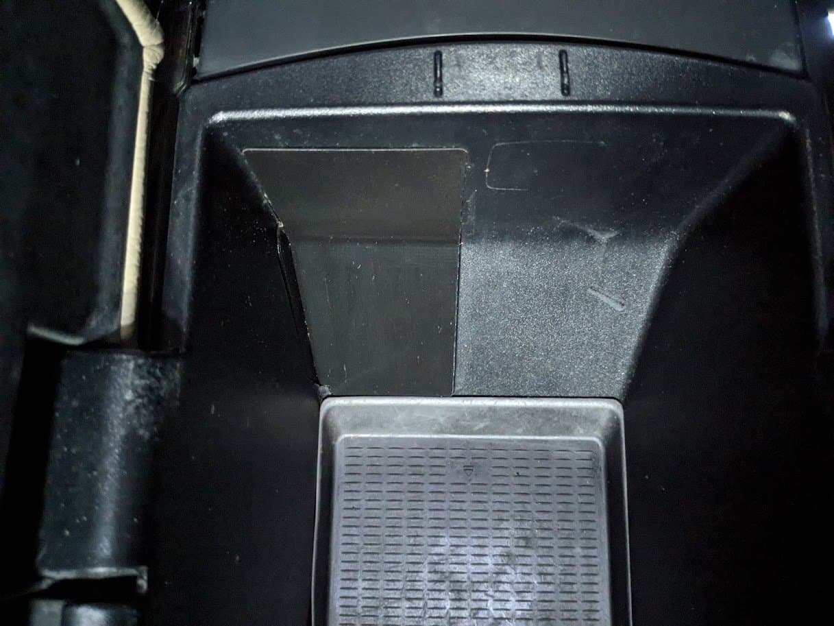
BMW X5 E70 Center Console Blind Plate
BMW
License: CC BY
View & download STL files
